
Finite Element Analysis (FEA) of a Remington Model 7 in 243 Win Caliber Using The LS-DYNA Software.
The FEA model of the Remington Model 7 action including the bolt, action, recoil
lug, and barrel. The model has 2 planes of symmetry.
This view is rotated shows the bolt lugs and brass with the barrel and action
removed.
The following conditions were used for the analysis.
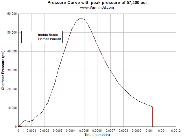
Pressure vs time curve used in the calculation. Note the early estimated
pressure rise in the primer pocket. Then the primer pocket and brass see the
same pressure. At 0.001025 seconds the pressure goes to zero and at 0.0011 the
contact surfaces are remove so that at 0.00121 the brass is free standing. There
is still some ringing going on but there is no contact.
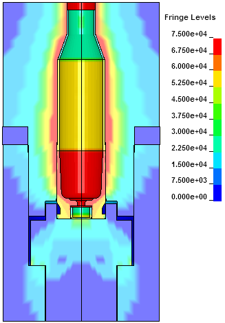
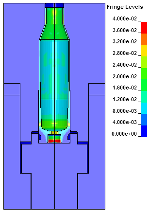
Fringes of effective stress at the time of the 57,400 psi peak pressure.
Fringes of plastic strain at the peak pressure of 57,400 psi.
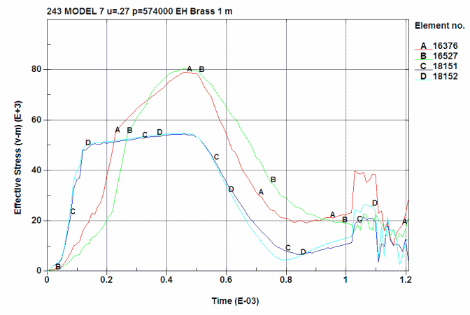
Effective Stress in the brass at 4 locations. All stresses are in psi.
A is ID at the 0.280 position (16376)
B is OD at the 0.280 position (16527)
C is ID at just below the shoulder junction (18152)
D is OD at just below the shoulder junction (18151)
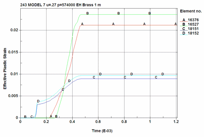
Plastic strain in the brass at 4 locations:
A is ID at the 0.280 position (16376)
B is OD at the 0.280 position (16527)
C is ID at just below the shoulder junction (18152)
D is OD at just below the shoulder junction (18151)
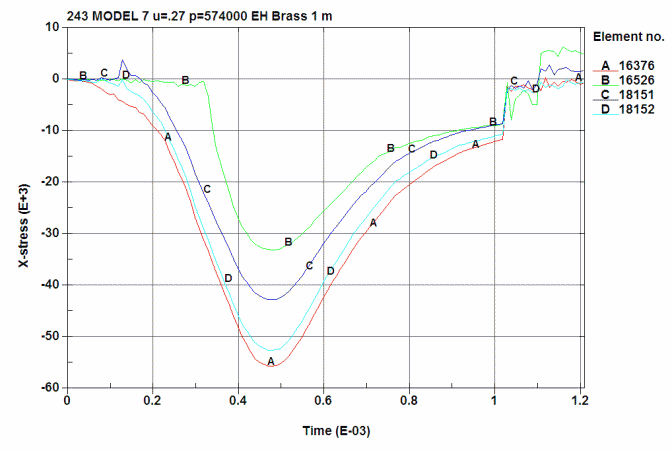
Radial Stress in the brass at 4 locations:
A is ID at the 0.280 position (16376)
B is OD at the 0.280 position (16526)
C is ID at just below the shoulder junction (18152)
D is OD at just below the shoulder junction (18151)
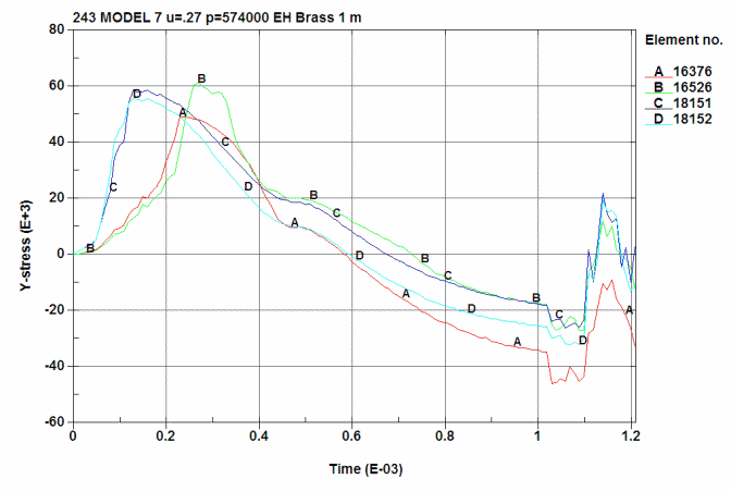
Hoop Stress in the brass at 4 locations:
A is ID at the 0.280 position (16376)
B is OD at the 0.280 position (16526)
C is ID at just below the shoulder junction (18152)
D is OD at just below the shoulder junction (18151)
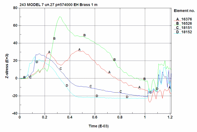
Axial Stress in the brass at 4 locations:
A is ID at the 0.280 position (16376)
B is OD at the 0.280 position (16526)
C is ID at just below the shoulder junction (18152)
D is OD at just below the shoulder junction (18151)
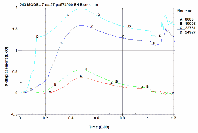
Radial displacement in the brass and chamber. All displacement are in inches.
A is ID of the chamber at the 0.280 point. (8688)
B is ID of the chamber just below the junction of the shoulder. (10008)
C is the OD of the brass at the 0.280 point. (22751)
D is the OD of the brass just below the junction of the shoulder. (24927)
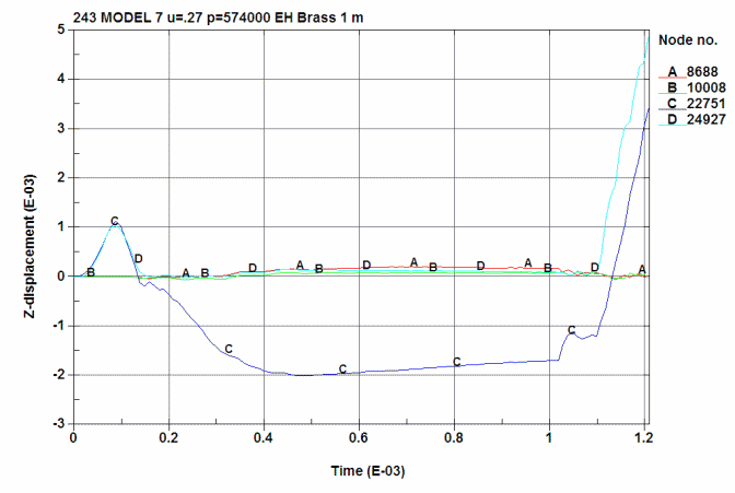
Axial displacement in the brass and chamber. The early blip in axial
displacement comes from the early pressure in the primer pocket. This drives the
case forward in the chamber (curves C and D). The brass case has increases in
length by 0.002" at the end of the event.
A is ID of the chamber at the 0.280 point. (8688)
B is ID of the chamber just below the junction of the shoulder. (10008)
C is the OD of the brass at the 0.280 point. (22751)
D is the OD of the brass just below the junction of the shoulder. (24927)
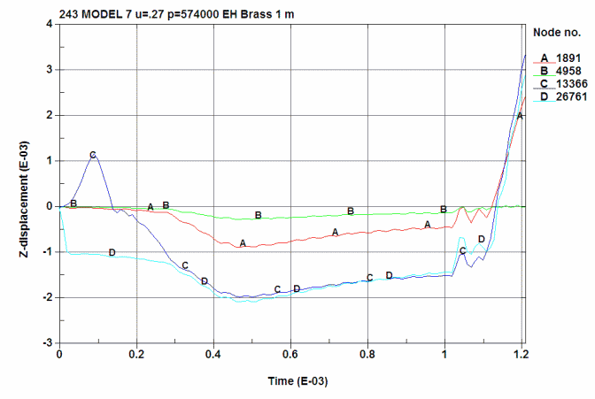
Axial displacement of the following:
A is the center of the bolt face. (1891)
B is the action's shelf where the bolt lug rests. (4958)
C is the base of the brass head. (13366)
D is the center of the primer cup. (26761)
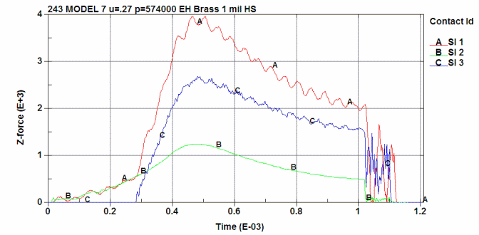
Finally, the axial loads in lbs vs time:
A Total load on the bolt lugs.
B Primer load on the bolt face.
C Brass head load on the bolt face.
The full model with 2 planes of symmetry. The model reflected on the left.
The bolt and 243 Win Brass. The bolt and 243 Win Brass with 2 planes reflected.
This shows the action and where the bolt lug rests.
Mesh Detail. Fine mesh in the areas of interest.
234 Win Brass Head and Primer.
Case Head Expansion vs Peak Chamber Pressure
Some who reload their ammo measure the expansion of the unsupported area of the case head with a micrometer. This allows them to determine the maximum load for a particular bullet and powder combination in their rifle. I used the Model 7 action with the 243 Win caliber brass to calculate case head expansion for increases in peak pressure.
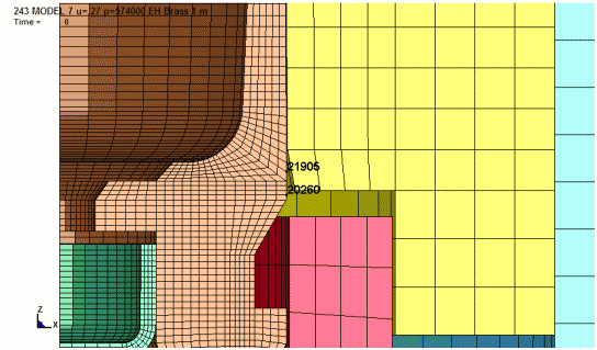
To determine the amount of permanent case head expansion, node 21905 was
selected and the increase in diameter at this location is plotted. The plots
show the case head expansion during firing and finally, the permanent increase
in diameter after firing. The location at node 20260 typically has about
0.0005" less expansion.
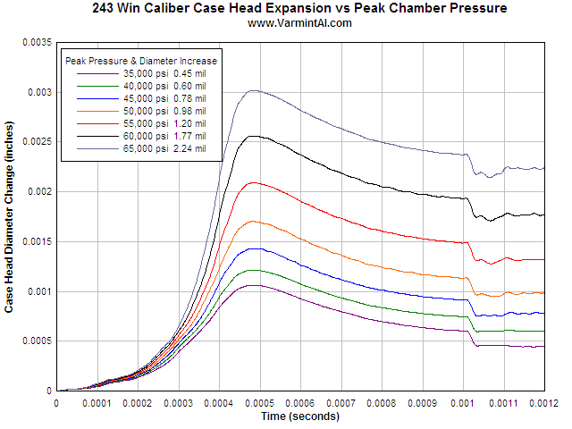
This plot shows the case head diameter increase as the pressure rises and then
the spring back as the pressure falls off to zero. The permanent diameter
increase is at the final time when the pressure is zero and the contact surfaces
are removed to simulate a free standing piece of brass. The conditions of this
series of calculations were as follows:
Cartridge Brass Properties
| Material Name and Condition. | Density lb/in^3 |
Youngs Modulus msi |
Poisson's Ratio |
Yield
Stress ksi |
Ultimate Stress ksi |
Elongation % |
Reduction in area % |
CTE per °F |
Yield
Offset % |
| Cartridge Brass Cu.7 Zn.3 dead soft | 0.308 | 16.0 | 0.33 | 11.0 | 44.0 | 68.0 | - | 11.10 | 0.50 |
| Cartridge Brass Cu.7 Zn.3 annealed | 0.308 | 16.0 | 0.33 | 19.0 | 51.0 | 55.0 | - | 11.10 | 0.50 |
| Cartridge Brass Cu.7 Zn.3 1/4 hard | 0.308 | 16.0 | 0.33 | 40.0 | 54.0 | 43.0 | - | 11.10 | 0.50 |
| Cartridge Brass Cu.7 Zn.3 1/2 hard | 0.308 | 16.0 | 0.33 | 52.0 | 62.0 | 23.0 | - | 11.10 | 0.50 |
| Cartridge Brass Cu.7 Zn.3 H04 full hard | 0.308 | 16.0 | 0.33 | 63.0 | 76.0 | 8.0 | - | 11.10 | 0.50 |
| Cartridge Brass Cu.7 Zn.3 H06 ex hard | 0.308 | 16.0 | 0.33 | 65.0 | 86.0 | 5.0 | - | 11.10 | 0.50 |
WHAT IS EFFECTIVE STRESS?.... Here is some information on Effective Stress or often referred to as Von Mises Stress. In structures under load, the stress state is not a simple uniaxial state of stress but a more complex triaxial state of stress. Plastic deformations (also called plastic flow) will occur in a material when the effective stress, seff exceeds the uniaxial yield stress. Here is the equation for the effective stress when a triaxial state of stress exists and s1, s2, and s3 are the principal stresses in the three orthogonal directions. The effective strain is eeff.
seff = (2½/2) [(s1—s2)2 + (s2—s3)2 + (s3—s1)2]½
eeff = (2½/3) [(e1—e2)2 + (e2—e3)2 + (e3—e1)2]½
1. When all three orthogonal stresses are equal (hydrostatic stress
state), the effective stress is zero. There is no yielding.
2. When s2
and s3
are zero, then the effective stress is the uniaxial stress. This is the stress
condition of an axial pull test specimen.
Looking at the equation, one can see some interesting concepts. If there is no
tension, but sufficient biaxial compression in the other two directions, then
there could be axial yielding in extension in the third direction. (This is like
squeezing a cylinder of putty in your hand and having it squirt out each end).
WHEN YIELDING OCCURS.... One can visualize yielding as a cylinder in
3-D space. The axis of the cylinder is the line of the hydrostat. It is a line
where s1=
s2=
s3.
When the triaxial stress state deviates from the hydrostat line but stays within
the cylinder, there is no yielding. When the triaxial stress state deviates from
the hydrostat outside of the cylinder then yielding occurs.
NO YIELDING IN HYDROSTATIC COMPRESSION.... When a metal is in hydrostatic
compression (immersed in a fluid and the pressure increased), there is no
yielding, no matter how high the pressure. With a real material, micro voids
would be closed and at extremely high pressures, the crystal structure
could be changed, such as converting carbon to a diamond. These pressures are
beyond those normally considered in engineering analysis of the strength of
structures.
NO YIELDING IN HYDROSTATIC TENSION.... When a metal is in hydrostatic
tension, in theory, there is no yielding. I can't think of any realistic way to
apply extremely high hydrostatic tensions. The limiting point would be the bond
strength of the atoms in the crystals.
Finally... The unsupported portion of the cartridge case heads are in a
complicated triaxial stress state at each location and the FEA codes determine
this for each tiny element. The back-of-the-envelope p/a type calculations are
of little value in accurately predicting and understanding what is happening
during loading such structures where a triaxial state of stress exists.
For the serious reader: How
to Check Another Engineer's Calculation.![]()

|
|
||||
|
|
Last Updated: 02/08/2013
Good Hunting... from Varmint Al![]()