
Rifle Chamber Finish & Friction Effects
on Bolt Load and Case Head Thinning.
FEA Calculations done with LS-DYNA
WINCHESTER 243 BRASS.... The 2D mesh rotated into a 3D picture. The calculations were actually performed in 2D since there is a axis of symmetry. The brass is the 243 Winchester caliber and the dimensions were taken from a sectioned Winchester brand empty brass. The brass at the neck and shoulder is in the Annealed condition. For the walls and case head, the brass is in the Full Hard condition. The material properties are listed below.
POWERFUL TOOL.... The LS-DYNA Finite Element Code by Livermore Software Technology Corp is a very powerful tool for calculating the dynamics of 2D axisymmetric structures as well as 3D structures. LS-DYNA was used to calculate the resulting plastic deformations and loads for a 243 Win Winchester brass rifle cartridge case pressurized with a 55,000 psi chamber pressure data. Each calculation used the same geometry and pressure loading and only the coefficient of friction between the cartridge case's wall and the rifle chamber was changed. Some earlier calculations were done with a ramp pressure curve. Early Calculations.
MATERIALS AND GEOMETRY.... Each calculation took about 5 minutes to run on my Athlon XP 64 computer at 2.4GHz CPU speed. It took about 3 days to generate the mesh from the the photograph, scale it to the correct size, and adjust the mesh density to be finely divided at the points of interest and still have enough reasonable detail in the rest of the geometry. The brass case head and walls were full hard cartridge brass with a yield of 63 ksi and an ultimate of 76 ksi. The cartridge case's shoulder and neck were of annealed cartridge brass with a yield of 19 ksi and an ultimate of 51 ksi. The primer was annealed cartridge brass. The barrel material was 416 stainless steel and was fixed in the vertical direction for 1.25" simulating the thread where the barrel joins the rifle action. The bolt face was 4140 steel that was fixed in the axial direction at its lower surface. There was an ~0.002" radial clearance between the brass and the chamber. There was a 0.006" axial clearance between the brass case head and the bolt surface. This clearance was used to simulate the bolt lug deflection that occurs during firing. The firing pin was not included in the model merely to simplify mesh generation.
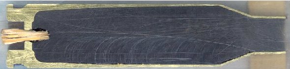
THE SECTIONED CASE.... Dick Hatfield sectioned a 243 Win
Winchester case with his milling machine and scanned it so I could get the
dimensions.
Many places have the outside dimensions of various calibers, but this was the
only way I could get the internal dimensions.
The wooden plug was used to keep the clear epoxy from running out while he was
allowing the epoxy to cure.
 243 Win Winchester brass. Barrel Dia =1.25" Bolt Face is fixed. |
 Mesh 2-D Outline. Radial clearance between brass and barrel of ~0.002" The primer is a line to line fit. |
 Close up of the mesh detail at the brass case head and primer. Axisymmetric 2-D mesh with 1979 nodes, 1670 elements, 5 materials, and 5 automatic contact surfaces including friction. Gap of 0.006" from the bolt face to the brass case head. (simulates 0.002" clearance plus action and boltlug stretching during firing). |
|
RESULTS FOR A RANGE OF FRICTION COEFFICIENTS.... In each calculation, only the Coefficient of Friction was changed between the brass and the chamber. The plastic strain, case thinning, and bolt face loads were calculated for seven different static friction coefficients. I have tried to identify the friction coefficients by the approximate surface conditions. Dick Hatfield has completed a Coefficient of Friction Test to better quantify the Coefficients of Friction with surface conditions and lubrication. I have tried to identify the surface conditions that would give these Coefficients of Friction, but extensive testing would be required to quantify these numbers and surface conditions accurately. Friction coefficients below u = ~0.1 are very difficult if not impossible to achieve unless a film of grease is trapped between the surfaces.
WHAT IS THE FRICTION COEFFICIENT?.... The friction coefficient is a dimensionless number and is the ratio of the force to cause sliding divided by the normal force the object applies to the sliding surface. Imagine a block of wood setting on a table. If the coefficient of friction between the block of wood and the table surface is u = 0.6, for example, then if you push down with a 10 pound force on the block of wood, it would take a 6 pound force parallel to the table's surface to make the block slide across the table.
CONCLUSION.... A polished or low friction chamber decreases the plastic strain near the case head and reduces the chance of case head separation on subsequent reloads.
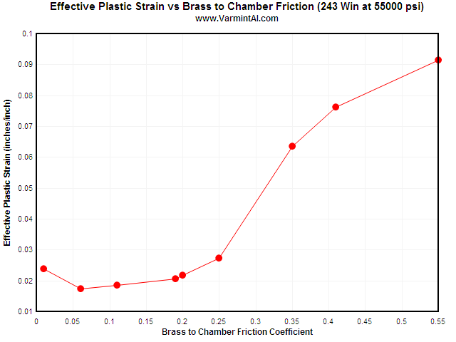
The maximum Effective Plastic Strain vs Coefficient of Friction between the 243
Win brass case and the 416 Stainless Steel chamber.
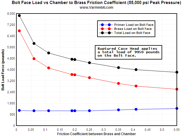
This chart summarizes the bolt load vs Coefficient of Friction between the brass case and the 416 stainless steel chamber's walls. A rough chamber might reduce the bolt load by 1000 pounds but increase the plastic strain in the brass case near the web. Rough chamber finish and/or excessive head space can cause "case head thinning" that eventually results in case head separation on subsequent reloads.
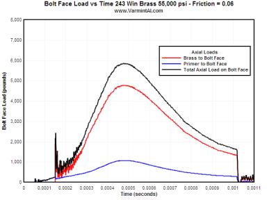
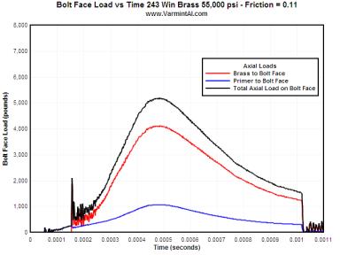
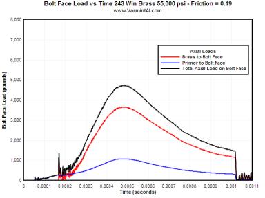
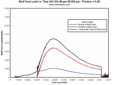
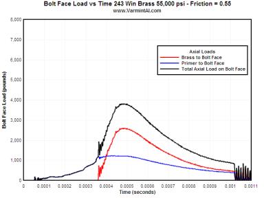
The following charts show the axial load on the bolt face for the primer, brass base, and the sum of the two for various friction conditions.
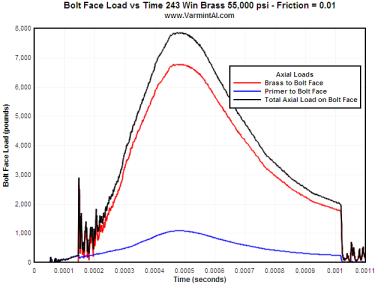


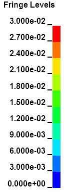
VERY LOW FRICTION.... Very low Coefficients of Friction of 0.01 to 0.11 are very difficult to obtain without extremely polished surfaces and grease. These two cases were calculated to complete the range of numbers and are not practical in the real world. Note that when there is extremely low friction not only does the bolt face load increase but the plastic strain in the case head also increases. There needs to be some axial tension in the wall of brass case wall to increase the resistance to yielding and formation of plastic strain. In each set of movie pictures of Effective Plastic Strain, the picture on the left is the actual deformations and the movie on the right has the deformations amplified by 10X so the deformations can more easily be seen. The same fringe levels for Effective Plastic Strain were used for each movie.
POLISHED AND LUBRICATED.... This level of friction would
represent what one would expect with a polished chamber and a lightly oiled
brass for Fire Forming. But one would not necessarily use a full 55,000 psi load
for fire forming. Note that in the cases with Coefficient of Friction of from
0.01 to 0.10 the brass head contacts the bolt face at about 150 microseconds. The
primer contacts the bolt face at about 50 microseconds. There was no firing pin
or firing pin forces in the calculations.

POLISHED DRY CHAMBER.... This is the condition of dry brass and a polished chamber. The peak total load on the bolt face is 4720 pounds. The maximum effective plastic strain is only 0.02 in/in in the case wall where thinning usually occurs. There is very little thinning of the brass forward of the web.
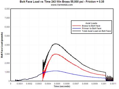
SANDPAPER FINISH.... For a 300 to 600 grit sandpaper finish on the chamber, the brass is sticking to the chamber walls and the case head contacts the bolt face much later in time. Once the brass "grabs" the chamber walls, the brass has to stretch before the case head contacts the bolt face. The bolt face load is reduced approximately 700 pounds lower than with the polished chamber.
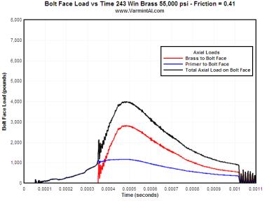
For a rough chamber finish, the brass has to stretch even more before the case
head contacts the bolt face.


For a very rough chamber with a 0.55 Coefficient of Friction the movie shows the
case stretching and thinning
where case head separations usually occurs.
| Coefficient of Friction | Peak Primer Load on Bolt Face (lb) | Peak Brass Head Load on Bolt Face (lb) | Total Peak Load on Bolt Face (lb) | Maximum Effective Plastic Strain near the Brass Web (in/in) |
| 0.01 | 1083 | 6775 | 7858 | 0.02384 |
| 0.06 | 1074 | 4783 | 5857 | 0.01741 |
| 0.10 | 1072 | 4113 | 5185 | 0.01859 |
| 0.19 | 1071 | 3659 | 4730 | 0.02054 |
| 0.20 | 1071 | 3638 | 4709 | 0.02178 |
| 0.25 | 1072 | 3424 | 4495* | 0.02728 |
| 0.35 | 1136 | 3010 | 4146 | 0.06350 |
| 0.41 | 1170 | 2831 | 4002 | 0.07626 |
| 0.55 | 1229 | 2603 | 3818 | 0.09144 |
* Peak Loads did not occur at the same time.
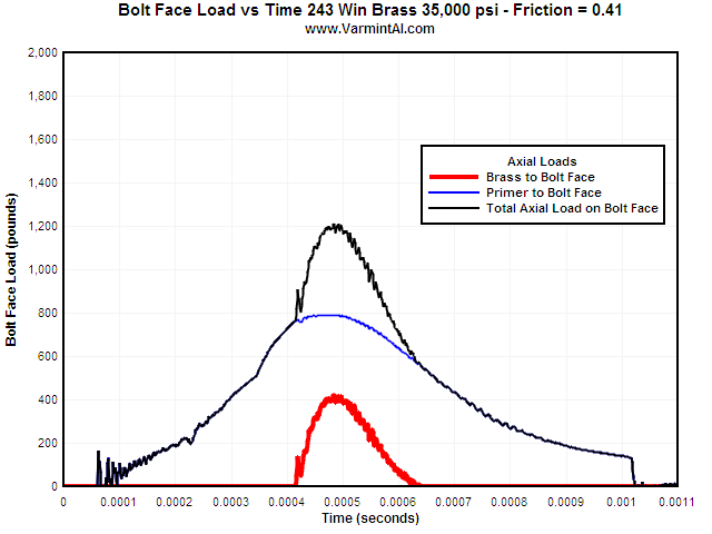
This chart shows the load on the bolt face for the same Win 243 brass but with a
peak chamber pressure of
35,000 psi. The high Coefficient of Friction of 0.41 "grabs" the brass
and it ends up applying less bolt load than
the primer applies.
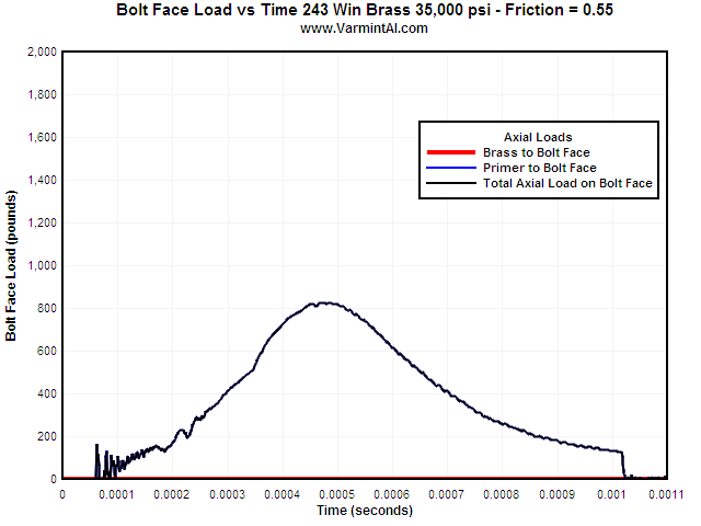
Increasing the Coefficient of Friction to 0.55 the brass case head never does
contact the bolt face for the
35,000 peak chamber pressure load. This condition would have the primer
protruding slightly.
Table 1: Coefficient of Friction for Various Surface Conditions of 416 Stainless Steel on Brass
| Estimated/Measured Coefficient of Friction (u) | Comments |
| 0.00 | For Case Head Separation (Hand calculation force = pressure * chamber ID area) |
| 0.01 | Friction this low is probably not physically possible and could be dangerous |
| 0.06 | Very low friction and shows the least plastic strain leading to case head thinning |
| 0.11* | Probably not possible: Polished chamber, polished brass with oil or grease |
| 0.19/0.19 | Polished chamber Flitz |
| 0.20/0.19 | Polished chamber Flitz |
| 0.25/0.27 | Smooth chamber, crocus cloth or smoother |
| 0.35/0.29 | Smooth chamber, 600 grit |
| 0.41/0.37 | Rough chamber finish, 320 grit finish (200 grit) |
| 0.55 | Very rough chamber, rough reamer finish with tool marks |
* Note: I am not suggesting using
lubricant on ammunition brass.
I am merely trying to identify how this low Coefficient of Friction might
possibly be obtained.
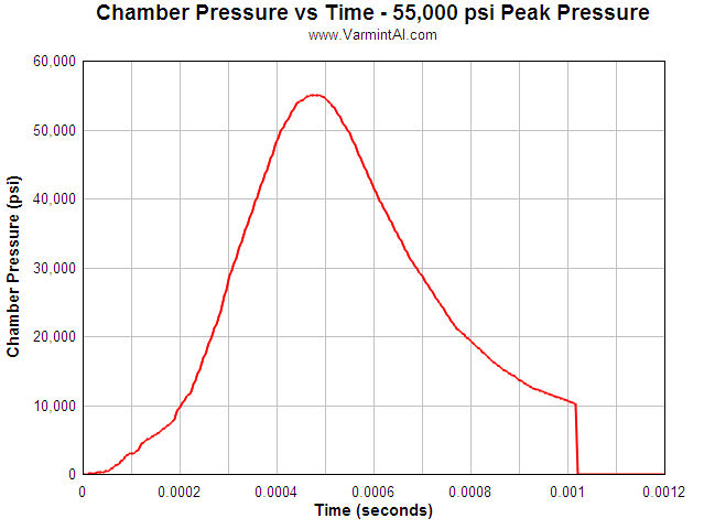
This is the generic chamber pressure vs time curve with a peak pressure of
55,000 psi that was used in the calculations. It is scaled from 6PPC pressure
data.
Table 2: The Power Law Plasticity material constants used for the 243 Win Brass in the calculations.
| Neck
and Shoulder of the 243 Winchester Brass
*MAT_POWER_LAW_PLASTICITY |
| Case Head and Cartridge Walls
*MAT_POWER_LAW_PLASTICITY |
| Coefficient of Friction Location | Coefficient of Friction Used |
| Brass Case Wall to Chamber | 0.01 to 0.55 as Indicated |
| Brass Shoulder and Neck to Chamber | 0.01 to 0.55 as Indicated |
| Primer to Primer Pocket | 0.30 |
| Primer to Bolt Face | 0.30 |
| Brass Head to Bolt Face | 0.30 |
Since the relative motions are extremely small, the static and
dynamic
coefficient of friction values are assumed to be the same.
Case Head Expansion vs Peak Chamber Pressure
Some reloaders measure the expansion of the unsupported area of the case head with a micrometer. This allows them to determine the maximum load for a particular bullet and powder combination in their rifle. I used the Model 7 action with the 243 Win caliber brass to calculate case head expansion for increases in peak pressure.
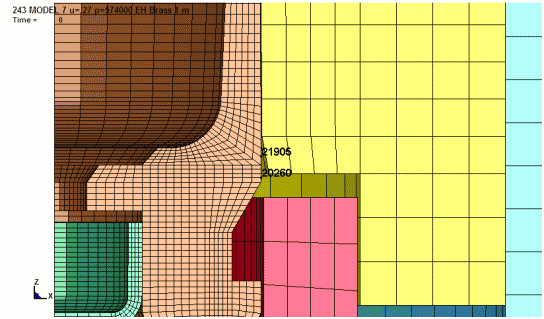
To determine the amount of permanent case head expansion, node 21905 was
selected and the increase in diameter at this location is plotted. The plots
show the case head expansion during firing and finally, the permanent increase
in diameter after firing. The location at node 20260 typically has about
0.0005" less expansion.
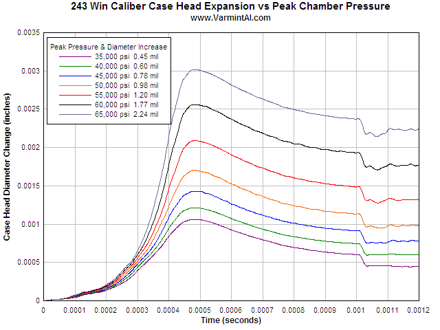
This plot shows the case head diameter increase as the pressure rises and then
the spring back as the pressure falls off to zero. The permanent diameter
increase is at the final time when the pressure is zero and the contact surfaces
are removed to simulate a free standing piece of brass. The conditions of this
series of calculations were as follows:
View the FEA model of the Remington Model 7 action including the bolt, action,
recoil lug, and barrel. The Analysis page is here.
Last Updated: 07/18/2015
Good Hunting... from Varmint Al
End of Page![]()